- 5 digit naca airfoil generator software#
- 5 digit naca airfoil generator code#
- 5 digit naca airfoil generator series#
- 5 digit naca airfoil generator windows#
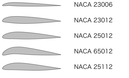
The program naca456 is a public domain program in modern Fortran for computing and tabulating the coordinates of the 4-digit, 4-digit modified, 5-digit, 6-series and 6A-series of NACA airfoils. For the purpose of this simulaton we are creating the airfoil along the YZ plane. The calculator below can be used to plot and extract airfoil coordinates for any NACA 4-series airfoil. In this case, it represents a force boundary, that is, the boundary where the flow over the whole airfoil deteriorated rapidly. Sorry, your blog cannot share posts by email. After you complete the sketch you can now transform the airfoil into a wing by pad or shell command available in the Body part design, Here’s a video tutorial which will make things more clear for you –, Your email address will not be published. 'naca airfoil wikipedia june 16th, 2018 - the naca airfoils are naca 4 amp 5 digit excel spreadsheets list of airfoils used by different aircraft database with images and coordinates of many airfoils ''creating wings in solidworks university of pennsylvania Pick values of x from 0 to the maximum chord c. From XFOIL documentation verbatim: "Some Fortran implementations will also choke on airfoil names that begin with T or F. Select Feuil1.main from the dropdown menu and the current Excel file.Click on Run. NACA 4-digit airfoil specification Fig: NACA 2412 Airfoil Cross-Section. The raw coordinates need cleaning up a little before we can import them into SOLIDWORKS.
5 digit naca airfoil generator software#
The entire risk as to the software applicability, performance and quality lies solely with you as the user and not.
5 digit naca airfoil generator series#
Continue reading "NACA 4 Series Airfoil Generator" Import airfoil coordinate files (.dat &. Now the coordinates (,) of the upper airfoil surface and (,) of the lower airfoil surface are x U = x L = x, y U = + y t, y L = − y t. Before learning about the nomenclature of the NACA 4-digit airfoil let’s learn about some basic airfoil terminologies. Before we can start simulating however, we need to design our aerofoil. This example uses Solidworks 2015, but it should work with any recent version of the software.
5 digit naca airfoil generator windows#
This video shows you the easiest way to create NACA airfoil coordinates using DesignFOIL, a neat Windows utility. One digit describing the distance of maximum thickness from the leading edge in tenths of the chord.Export all data directly to Excel spreadsheets with the push of a button or menu click.One digit describing the roundness of the leading edge, with 0 being sharp, 6 being the same as the original airfoil, and larger values indicating a more rounded leading edge.
5 digit naca airfoil generator code#
The following table presents the various camber-line profile coefficients:įour- and five-digit series airfoils can be modified with a two-digit code preceded by a hyphen in the following sequence: The formula for the shape of a NACA 00xx foil, with "xx" being replaced by the percentage of thickness to chord, is y t = 5 t, Plot of a NACA 0015 foil generated from formula The 15 indicates that the airfoil has a 15% thickness to chord length ratio: it is 15% as thick as it is long.Įquation for a symmetrical 4-digit NACA airfoil The NACA 0015 airfoil is symmetrical, the 00 indicating that it has no camber. įor example, the NACA 2412 airfoil has a maximum camber of 2% located 40% (0.4 chords) from the leading edge with a maximum thickness of 12% of the chord.


The NACA four-digit wing sections define the profile by: These figures and shapes transmitted the sort of information to engineers that allowed them to select specific airfoils for desired performance characteristics of specific aircraft. Engineers could quickly see the peculiarities of each airfoil shape, and the numerical designator ("NACA 2415," for instance) specified camber lines, maximum thickness, and special nose features. By 1929, Langley had developed this system to the point where the numbering system was complemented by an airfoil cross-section, and the complete catalog of 78 airfoils appeared in the NACA's annual report for 1933. According to the NASA website:ĭuring the late 1920s and into the 1930s, the NACA developed a series of thoroughly tested airfoils and devised a numerical designation for each airfoil - a four digit number that represented the airfoil section's critical geometric properties. NACA initially developed the numbered airfoil system which was further refined by the United States Air Force at Langley Research Center. 2.2 Equation for a cambered 4-digit NACA airfoil.2.1 Equation for a symmetrical 4-digit NACA airfoil.


 0 kommentar(er)
